Peugeot workshop manual Jet Force (756739) - Scootergrisen
Peugeot workshop manual Jet Force (756739) - Scootergrisen
Peugeot workshop manual Jet Force (756739) - Scootergrisen

Create successful ePaper yourself
Turn your PDF publications into a flip-book with our unique Google optimized e-Paper software.
SALES DIVISION<br />
NETWORK TECHNICAL INFORMATION<br />
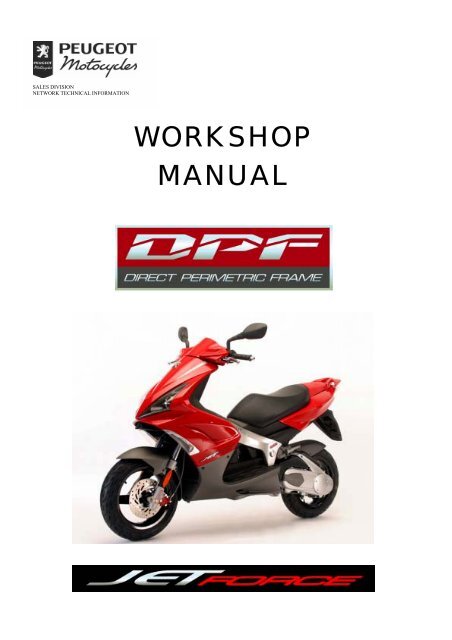
WORKSHOP<br />
MANUAL
CONTENTS<br />
CONTENTS<br />
CONTENTS.......................................................................................................................................... 2<br />
CHARACTERISTICS......................................................................................................................... 5<br />
Engine............................................................................................................................................................. 5<br />
Capacities ....................................................................................................................................................... 5<br />
Chassis markings............................................................................................................................................ 5<br />
Engine markings............................................................................................................................................. 5<br />
Frame.............................................................................................................................................................. 6<br />
Dimensions and weight .................................................................................................................................. 6<br />
Tyres............................................................................................................................................................... 6<br />
SERVICE SCHEDULE AND COMMISSIONING ......................................................................... 7<br />
Check.............................................................................................................................................................. 7<br />
Change............................................................................................................................................................ 7<br />
Check and lubricate........................................................................................................................................ 7<br />
Reading the ECU fault codes ......................................................................................................................... 7<br />
Test machine................................................................................................................................................... 7<br />
SPECIAL IMPORTANT POINTS .................................................................................................... 8<br />
Oil and fuel..................................................................................................................................................... 8<br />
Starting up after overhauling the engine ........................................................................................................ 8<br />
Electricity ....................................................................................................................................................... 8<br />
Special features............................................................................................................................................... 8<br />
TIGHTENING TORQUES................................................................................................................. 9<br />
Body panels .................................................................................................................................................... 9<br />
Frame.............................................................................................................................................................. 9<br />
Standard.......................................................................................................................................................... 9<br />
SPECIAL TOOLS ............................................................................................................................. 10<br />
INSTRUMENT CLUSTER............................................................................................................... 11<br />
Instrument cluster description ...................................................................................................................... 11<br />
Description of the multi-function display .................................................................................................... 12<br />
MULTI-FUNCTION DISPLAY FUNCTIONS AND SETTINGS................................................ 12<br />
Changing from the total distance display to the daily display ..................................................................... 12<br />
Changing the distance unit ........................................................................................................................... 13<br />
Setting the clock ........................................................................................................................................... 13<br />
Maintenance function................................................................................................................................... 14<br />
Fuel gauge self-diagnostic............................................................................................................................ 14<br />
CONTROL CABLE AND HARNESS ROUTINGS....................................................................... 15<br />
ABS/PBS panel ............................................................................................................................................ 15<br />
Conventional braking panel.......................................................................................................................... 15<br />
Right-hand side 50 cc................................................................................................................................... 16<br />
Left-hand side 125 cc ................................................................................................................................... 17<br />
Rear right...................................................................................................................................................... 18<br />
Rear centre.................................................................................................................................................... 18<br />
LOCATION OF COMPONENTS.................................................................................................... 19<br />
50 cc ............................................................................................................................................................. 19<br />
125 cc ........................................................................................................................................................... 20<br />
BODY .................................................................................................................................................. 21<br />
Location of body components (50 and 125 cc) ............................................................................................ 21<br />
Body component sequence of disassembly (50 and 125 cc)........................................................................ 21<br />
Removal of front lower legshields (50 and 125 cc) Procedure 1............................................................... 22<br />
Removal of the headlight and sidelight assemblies (50 and 125 cc)............................................................ 22<br />
Method for fitting the lower legshield bracket (50 and 125 cc)................................................................... 22<br />
Page : 2<br />
Reproduction or translation, even partial, are forbidden without the written consent of <strong>Peugeot</strong> Motocycles
CONTENTS<br />
Removal of the storage compartment (50 and 125 cc) Procedure 2........................................................... 23<br />
Removal of the shield)(50 and 125 cc) Procedure 3................................................................................... 23<br />
Removal of the rear cover assembly and mudflap (50 and 125 cc) Procedure 4 ....................................... 25<br />
Removal of the rear light / storage compartment trim (50 and 125 cc) ...................................................... 25<br />
FRAME............................................................................................................................................... 26<br />
Removal of the rear frame (50 cc)................................................................................................................ 26<br />
Removal of the frame (50 cc)....................................................................................................................... 27<br />
MISCELLANEOUS OPERATIONS ............................................................................................... 29<br />
Removal of the oil tank (50 cc) or oil separator (125 cc), the saddle lock (50 and 125 cc)......................... 29<br />
To remove the oil filter (50 cc) .................................................................................................................... 29<br />
To remove the header tank (50 and 125 cc) ................................................................................................. 29<br />
Removal of the radiator / radiator bracket (50 and 125 cc).......................................................................... 30<br />
Removal of the fuel gauge (50 cc) ............................................................................................................... 31<br />
Removal of the strainer (50 cc) .................................................................................................................... 32<br />
Removal of the fuel tank filler ring (50 and 125 cc).................................................................................... 33<br />
Removal of the fuel tank (50 cc).................................................................................................................. 33<br />
Removal of the central shock absorber / from the swingarm (50 and 125 cc)............................................. 34<br />
Removal of the radiator deflector (50 cc) .................................................................................................... 35<br />
Removal of the braking limiter (50 cc) ........................................................................................................ 35<br />
Removal of the saddle strut (50 and 125 cc)................................................................................................ 35<br />
WORKING ON THE ENGINE WITHOUT REMOVING THE ENGINE (50 cc) .................... 36<br />
Removal of the inlet coupling and valves .................................................................................................... 36<br />
To remove the cylinder head Procedure 5 .................................................................................................. 37<br />
Removal of the cylinder / piston .................................................................................................................. 37<br />
Removal of the temperature sensor.............................................................................................................. 38<br />
Removal of the air compressor..................................................................................................................... 38<br />
SPECIAL WORK AND PROCEDURES WITHOUT REMOVING THE ENGINE................. 39<br />
Procedure for reducing the fuel circuit pressure Procedure 6 (50 cc) ........................................................ 39<br />
Procedure for bleeding the fuel circuit Procedure 7 (50 and 125 cc)......................................................... 39<br />
Removal of the injection manifold (50 cc)................................................................................................... 40<br />
Removal of the air injector (50 cc)............................................................................................................... 40<br />
Removal of the thermostat (50 cc) ............................................................................................................... 41<br />
Removal of the ECU (50 and 125 cc) .......................................................................................................... 42<br />
Removal of the throttle unit (50 cc) ............................................................................................................. 42<br />
Removal of the oil pump (50 cc).................................................................................................................. 43<br />
Removal of the fuel gauge (50 cc) ............................................................................................................... 43<br />
ELECTRICITY.................................................................................................................................. 44<br />
Removal of the instrument cluster (50 and 125 cc)...................................................................................... 44<br />
Removal of the voltage regulator and saddle actuator (50 and 125 cc) ....................................................... 44<br />
Removal of the battery cover, battery, fuses (50 and 125 cc) ...................................................................... 44<br />
Removal of the starter motor and/or lighting relay (50 and 125 cc) and/or the fuel pump and/or<br />
ABS/PBS system relay (125 cc)................................................................................................................... 45<br />
Removal of the high tension coil (50 and 125 cc)........................................................................................ 45<br />
Removal of the horn, immobiliser module (50 and 125 cc)......................................................................... 45<br />
Removal of the transponder antenna (50 and 125 cc) .................................................................................. 46<br />
Removal of the starter motor (50 cc)............................................................................................................ 46<br />
ENGINE REMOVAL........................................................................................................................ 47<br />
Removal of the 50 cc engine ........................................................................................................................ 47<br />
125 cc SPECIFIC MISCELLANEOUS WORK ............................................................................. 48<br />
Removal of the idle valve............................................................................................................................. 48<br />
Removal of the thermostat ........................................................................................................................... 48<br />
Page : 3<br />
Reproduction or translation, even partial, are forbidden without the written consent of <strong>Peugeot</strong> Motocycles
Page : 4<br />
CONTENTS<br />
Removal of the engine temperature sensor .................................................................................................. 48<br />
Removal of the fuel injector......................................................................................................................... 49<br />
Removal of the oil pressure switch .............................................................................................................. 49<br />
Removal of the throttle unit.......................................................................................................................... 49<br />
Removal of the fuel pump / of the fuel gauge.............................................................................................. 51<br />
Removal of the starter motor........................................................................................................................ 52<br />
Removal of the rear brake pads or caliper.................................................................................................... 53<br />
Removal of the suspension arm.................................................................................................................... 53<br />
Removal of the engine mounting twin linkrod............................................................................................. 54<br />
Method of fitting the engine mounting twin linkrod.................................................................................... 55<br />
Removal of the motor-driven fan heat switch.............................................................................................. 56<br />
Removal of the motor-driven fan ................................................................................................................. 56<br />
125 cc SPECIFIC WORK REQUIRING ENGINE REMOVAL .................................................. 57<br />
Removal of the power unit Procedure 8 ..................................................................................................... 57<br />
Removal of the engine Procedure 9............................................................................................................ 58<br />
Removal of the rocker cover, setting the rockers, removal of the camshaft, removal of the rockers.......... 58<br />
Removal of the cylinder head, removal of the cylinder and/or piston, removal of the cylinder head or<br />
base gasket, removal of the timing chain, setting the timing ....................................................................... 58<br />
Removal of the connecting rod and/or LH bearing and/or changing the casings ........................................ 58<br />
Reproduction or translation, even partial, are forbidden without the written consent of <strong>Peugeot</strong> Motocycles
CHARACTERISTICS<br />
Engine<br />
CHARACTERISTICS<br />
50 cc 125 cc<br />
Type<br />
Single cylinder 2-stroke direct<br />
injection<br />
Single cylinder 4-stroke indirect<br />
injection<br />
Cooling Liquid<br />
Bore x stroke 39.9 x 39.8 mm 57 x 48.9 mm<br />
Cubic capacity 49.9 cc 124.8 cc<br />
Max. power<br />
output<br />
3.6 kW at 7500 rpm 9.2 kW at 8750 rpm<br />
Max. torque at 6500 rpm 7250 rpm<br />
Fuel system<br />
Direct electronic injection<br />
(TSDI)<br />
Indirect electronic injection<br />
(EFI)<br />
Lubrication Electric oil pump Trochoidal pump<br />
Transmission 2 variable pulleys and Vee belt<br />
Clutch Centrifugal automatic<br />
Spark plug NGK CPR8E NGK CR7EB<br />
Exhaust Catalytic Non-catalytic<br />
Capacities<br />
Fuel tank 8 litres 95 or 98 lead-free<br />
Oil tank 1.2 litres semi-synthetic (API TC)<br />
Engine oil 1.25 litres SAE 10W40<br />
Relay box oil 0.12 litres SAE 80W90 Life lubricated<br />
Coolant* 1.3 l 1.6 l<br />
Fork<br />
* <strong>Peugeot</strong> coolant part number 754614<br />
Chassis markings<br />
1 – VIN number and manufacturer’s plate<br />
125 cc by tube Esso Univis 46<br />
or Agip H Lift 46<br />
Engine markings<br />
2 – Engine number<br />
Reproduction or translation, even partial, are forbidden without the written consent of <strong>Peugeot</strong> Motocycles<br />
190 cc by tube Esso Univis 46<br />
or Agip H Lift 46<br />
Page : 5
Frame<br />
CHARACTERISTICS<br />
50 cc 125 cc<br />
Frame Direct Perimetric Frame<br />
Front suspension Ø 32 mm telescopic fork Ø 36 mm telescopic fork<br />
Travel 85 mm 95 mm<br />
Rear suspension Central shock absorber<br />
Travel 95 mm 90 mm<br />
Dimensions and weight<br />
Overall length 1914 mm 1918 mm<br />
Width at<br />
handlebar<br />
740 mm<br />
Height with rear<br />
view mirror<br />
1260 mm 1279 mm<br />
Wheelbase 1314 mm 1369 mm<br />
Ground clearance 137 mm 112 mm<br />
Saddle height: 820 mm 845 mm<br />
Unladen weight 115 kg 149 kg<br />
Tyres<br />
Front wheel 13-inch alloy<br />
Front tyre 130/60 - 13<br />
Front tyre<br />
2 bar 2 bar<br />
pressure<br />
Rear wheel 13-inch alloy<br />
Rear tyre 130/60 - 13 140/60 - 13<br />
Rear tyre pressure 2.2 bar 2.2 bar<br />
Page : 6<br />
Reproduction or translation, even partial, are forbidden without the written consent of <strong>Peugeot</strong> Motocycles
SERVICE SCHEDULE AND COMMISSIONING<br />
SERVICE SCHEDULE AND COMMISSIONING<br />
Heavy duty servicing is for vehicles used under “harsh” conditions: door-to-door deliveries, intensive<br />
urban use (courier), short journeys with engine cold, dusty areas, ambient temperature over 30°C.<br />
Service operations 500 kms Every 5000 kms Every 10000 kms<br />
or 1 months or 12 months<br />
Heavy duty servicing<br />
Check<br />
500 kms Every 2500 kms Every 5000 kms<br />
Throttle cable play X X X<br />
Steering column play X X X<br />
Operation of electrical equipment X X X<br />
Condition of front and rear brake hydraulic<br />
controls<br />
X X X<br />
Condition of fuel pipes X X X<br />
Condition of oil pipes X X X<br />
Tyre pressures X<br />
Tyre condition, pressure and wear X X<br />
Brake fluid level X X X<br />
Battery electrolyte level * X X X<br />
Coolant level X X X<br />
Engine oil level X<br />
Tightness of nuts and bolts X X X<br />
Change<br />
Spark plug X X<br />
Inlet silencer/air filter**<br />
Front brake pads# X<br />
Rear brake pads *# X<br />
Drive pulley bearings and guides # X X<br />
Transmission belt X<br />
Engine oil (+ clean strainer) X<br />
Engine oil filter X<br />
Brake fluid and coolant**<br />
Check and lubricate<br />
Driven pulley: moving flange and needle<br />
bush<br />
X<br />
Drive pulley: moving flange and rollers* X<br />
Reading the ECU fault codes<br />
Injection and ABS/PBS system* X X X<br />
Test machine<br />
On road X X X<br />
* depending on equipment<br />
# if necessary<br />
** every 20000 km for the 50 cc (10000 if harsh use servicing) and every 40000 for the 125 cc (20000<br />
km if harsh use servicing)<br />
Reproduction or translation, even partial, are forbidden without the written consent of <strong>Peugeot</strong> Motocycles<br />
Page : 7
SPECIAL IMPORTANT POINTS<br />
Page : 8<br />
SPECIAL IMPORTANT POINTS<br />
Oil and fuel<br />
This engine is designed to run on 95 or 98 unleaded fuel only<br />
Never run the machine with a petrol/oil mixture.<br />
The oil used for the separate lubrication system is « Esso 2T Spécial » or « Esso 2T Spécial antifumée<br />
» recommended by the manufacturer<br />
Starting up after overhauling the engine<br />
The oil circuit bleed system (50 cc) must be checked with the diagnostic tool, the fuel pump bleeds itself<br />
automatically when the ignition is turned on<br />
Starting should not be with a 2-stroke mixture, as the fuel pump and injectors are not designed to<br />
operate with oil.<br />
When starting the engine hot or cold do not accelerate<br />
Check the coolant level in the header tank<br />
After road-testing the machine, check there are no fault codes left in the ECUs (read with diagnostic<br />
tool)<br />
Electricity<br />
All components of the electrical system are powered with 12 volts DC.<br />
The battery must not be disconnected while the engine is running and the voltage must be at least 8.5<br />
volts for the ECU to function and enable engine starting<br />
To avoid any risk of forgetting to turn off the ignition after opening the saddle, the ignition key<br />
should be removed after each job<br />
Special features<br />
After changing the injection ECU or the throttle, the initialisation procedure must be carried out with the<br />
diagnostic tool<br />
The ECU has a diagnostic function which via the instrument cluster Led or the diagnostic tool, enables<br />
reading of the faults in the memory<br />
The fuel inlet and injection manifold return pipes must only be replaced by genuine service parts.<br />
The fuel pressure of 8 bars requires special pipes.<br />
The fuel pipes must be changed if they show signs of wear, cracks, etc.<br />
The clips are specific, they must always be changed each time they are removed and replaced with<br />
new genuine parts clips<br />
Note:<br />
Before carrying out any work, leave the engine to cool for a minimum of 2 hours.<br />
Petrol is highly inflammable, do not smoke in the working area and avoid proximity to flames or sparks.<br />
Work in a clear and well-ventilated area.<br />
Reproduction or translation, even partial, are forbidden without the written consent of <strong>Peugeot</strong> Motocycles
TIGHTENING TORQUES<br />
Body panels<br />
TIGHTENING TORQUES<br />
Front mudguard 0.8 to 1.2 mdaN<br />
Handlebar cover 0.2 to 0.4 m.daN<br />
Front legshields 0.2 to 0.4 m.daN<br />
Rear shield 0.2 to 0.4 m.daN<br />
Bottom panel 0.2 to 0.4 m.daN<br />
Footboard 0.4 to 0.6 m.daN<br />
Saddle storage compartment 0.4 to 0.6 m.daN<br />
Rear panels 0.2 to 0.4 m.daN<br />
Grab handle 2 to 2.5 m.daN<br />
Rear mudguard 0.2 to 0.4 m.daN<br />
Frame<br />
Front wheel spindle 6 to 7 m.daN<br />
Rear wheel bolt 8.5 to 9.5 m.daN<br />
Rear wheel spindle nut 10 to 12 m.daN<br />
Linkrod to engine pivot 4.3 to 5 m.daN<br />
Linkrod to swingarm 4.3 to 5 m.daN<br />
Engine-upper linkrod pivot 4.3 to 5 m.daN<br />
Shock absorber top mount 2.4 to 2.6 m.daN<br />
Shock absorber bottom mount 2.4 to 2.6 m.daN<br />
Front and rear frame mounting nut 2 to 2.5 m.daN<br />
Exhaust to cylinder mounting nut 1.5 to 1.8 m.daN<br />
Exhaust to cylinder head mounting nut (125 cc) 1.5 to 1.8 m daN<br />
Exhaust to casing mounting bolt 2 to 2.5 m.daN<br />
Upper cone (in 2 operations) 3.8/2.3 mdaN<br />
Upper cone locknut Tighten <strong>manual</strong>ly<br />
Steering locknut 7 to 8 m.daN<br />
Front brake caliper 2.5 to 3.5 m.daN<br />
Rear brake caliper 2 to 2.5 m.daN<br />
Front disc brake 0.9 to 1 m.daN<br />
Rear disc brake 0.9 to 1 m.daN<br />
Handlebar 2.5 to 3.5 mdaN<br />
Standard<br />
Nut and bolt 5 mm diameter 0.5 m.daN<br />
Nut and bolt 6 mm diameter 1 m.daN<br />
Nut and bolt 8 mm diameter 2.2 m.daN<br />
Nut and bolt 10 mm diameter 3.5 m.daN<br />
Nut and bolt 12 mm diameter 5.5 m.daN<br />
Reproduction or translation, even partial, are forbidden without the written consent of <strong>Peugeot</strong> Motocycles<br />
Page : 9
SPECIAL TOOLS<br />
Page : 10<br />
. Tool N° Description Used with<br />
68994 Torque wrench 8<br />
Nm to 54 Nm<br />
750539 Tie-wrap pliers<br />
SPECIAL TOOLS<br />
extension<br />
752235<br />
adapter<br />
752236<br />
752235 1/2 extension 69802 or<br />
753977<br />
752236 1/2-3/8 adapter 69802 or<br />
753978<br />
753977 Torque wrench<br />
30 Nm to 150<br />
Nm<br />
754086 Steering tool<br />
extension<br />
752235<br />
adapter<br />
752237<br />
755806 Cartridge France 755878<br />
755807 Cartridge Export 755878<br />
755878 Diagnostic tool<br />
(game boy<br />
colour)<br />
755806<br />
755807<br />
Reproduction or translation, even partial, are forbidden without the written consent of <strong>Peugeot</strong> Motocycles<br />
755990 Diagnostic tool<br />
update software<br />
755996 hose clamp<br />
756017 petrol injection<br />
power supply<br />
harness<br />
756715 Tank gauge spanner<br />
756449 ABS/PBS interface<br />
cable for diagnostic<br />
tool<br />
756575 Piston locking fork<br />
756716 Tank ring spanner<br />
756607 Fork seal fitting tool<br />
125 cc<br />
756608 Fork seal fitting tool<br />
50 cc<br />
755878<br />
755806<br />
755807
INSTRUMENT CLUSTER<br />
Instrument cluster description<br />
INSTRUMENT CLUSTER<br />
1. Multi-function display<br />
2. Rev counter<br />
3. Speedometer<br />
4. Engine temperature gauge<br />
5. Control button<br />
6. Injection system diagnostic warning light<br />
7. Transponder immobiliser dissuasion light<br />
8. ABS/PBS system diagnostic warning light (125 cc)<br />
9. Headlight warning light<br />
10. Low oil level (50 cc) or oil pressure (125 cc) warning light<br />
11. Direction indicator warning light<br />
12. Battery charge warning light<br />
When the ignition is turned on, the different functioning tests are carried out automatically for 5<br />
seconds:<br />
- Display of all of the multi-function display items (1) and the speed (3)<br />
- Lighting of all the warning lights (except ABS/PBS depending on version)<br />
- Test of rev counter stepper motors (2) and engine temperature (4) giving one sweep of the needles and<br />
zero reset where necessary<br />
Reproduction or translation, even partial, are forbidden without the written consent of <strong>Peugeot</strong> Motocycles<br />
Page : 11
Description of the multi-function display<br />
13. Tripmeter (total or daily)<br />
14. Tripmeter display<br />
15. Type of unit used by the tripmeter<br />
16. Clock<br />
17. Maintenance indicator (spanner symbol)<br />
18. Fuel gauge<br />
Page : 12<br />
INSTRUMENT CLUSTER<br />
MULTI-FUNCTION DISPLAY FUNCTIONS AND SETTINGS<br />
Setting and function change operations can only be carried out if the machine is stationary (engine<br />
not running) This is for safety reasons.<br />
Changing from the total distance display to the daily display<br />
The tripmeter (13) has two functions:<br />
- Total distance (15) displays and memorises the total distance covered by the machine<br />
- The tripmeter (14) displays and memorises the distance covered over a given period<br />
With the ignition on, changeover from the main to the daily distance and inversely is by briefly pressing<br />
the control button (5)<br />
With the ignition on, reset of the daily tripmeter is by pressing the control button for more than 3<br />
seconds<br />
Reproduction or translation, even partial, are forbidden without the written consent of <strong>Peugeot</strong> Motocycles
INSTRUMENT CLUSTER<br />
Changing the distance unit<br />
Changing the distance unit (km or miles) is as follows:<br />
- Ignition off, hold down the control button (5) and turn on the ignition, the distance unit flashes<br />
- Select the unit by briefly pressing the control button, the distance unit changes from “km” to “miles”<br />
or inversely.<br />
-Turn off ignition to confirm<br />
Setting the clock<br />
The time can only be set in the tripmeter total distance position<br />
- Ignition on, press the button (5) until the time flashes<br />
- Set the time by successive pushes on the control button<br />
- To change the tenths of a minute, press the button until the minute tenths flash<br />
- Change the minute tenths by pressing as required on the button<br />
- Proceed in the same way to set the minutes<br />
- Press the button for more than 3 seconds to validate the clock setting<br />
Reproduction or translation, even partial, are forbidden without the written consent of <strong>Peugeot</strong> Motocycles<br />
Page : 13
INSTRUMENT CLUSTER<br />
Maintenance function<br />
Every 5000 km a « spanner » symbol appears informing the rider that his machine is due for service<br />
After servicing the machine, erase the spanner symbol as follows:<br />
- Ignition off, hold down the button (5) and turn on the ignition, the spanner symbol flashes<br />
- Release the control button<br />
- Press the button again for at least 5 seconds, the spanner symbol goes off<br />
Fuel gauge self-diagnostic<br />
If the fuel system is cut off from the fuel gauge, when the ignition is turned on, the display segments<br />
light one after the other<br />
Page : 14<br />
Reproduction or translation, even partial, are forbidden without the written consent of <strong>Peugeot</strong> Motocycles
CONTROL CABLE AND HARNESS ROUTINGS<br />
CONTROL CABLE AND HARNESS ROUTINGS<br />
ABS/PBS panel<br />
Conventional braking panel<br />
1. Main harness<br />
2. Throttle control<br />
3. Transponder antenna<br />
4. Speed sensor<br />
5. Brake light switch<br />
6. ABS/PBS brake module reservoir feed pipe<br />
7. Rear brake pipe<br />
8. Right master cylinder to module brake pipe<br />
9. Module brake pipe to front caliper<br />
10. Left master cylinder to module brake pipe<br />
1. Main harness<br />
2. Throttle control<br />
3. Transponder antenna<br />
4. Speed sensor<br />
5. Brake light switch<br />
6. Front brake pipe<br />
7. Rear brake pipe<br />
Reproduction or translation, even partial, are forbidden without the written consent of <strong>Peugeot</strong> Motocycles<br />
Page : 15
Right-hand side 50 cc<br />
Page : 16<br />
CONTROL CABLE AND HARNESS ROUTINGS<br />
1. Main harness<br />
2. Throttle cable (50 cc)<br />
3. Transponder antenna<br />
4. Speed sensor<br />
5. Front brake pipe<br />
6. Rear brake pipe<br />
7. Fuel feed pipe<br />
Reproduction or translation, even partial, are forbidden without the written consent of <strong>Peugeot</strong> Motocycles
Left-hand side 125 cc<br />
CONTROL CABLE AND HARNESS ROUTINGS<br />
1. Main harness<br />
2. Throttle cable (125 cc)<br />
3. Rear brake pipe<br />
4. Fuel supply pipe<br />
5. Air pressure slave pipe<br />
6. Fuel overflow pipe<br />
Reproduction or translation, even partial, are forbidden without the written consent of <strong>Peugeot</strong> Motocycles<br />
Page : 17
Rear right<br />
1. Main harness<br />
Rear centre<br />
1. Main harness<br />
Page : 18<br />
CONTROL CABLE AND HARNESS ROUTINGS<br />
Reproduction or translation, even partial, are forbidden without the written consent of <strong>Peugeot</strong> Motocycles
LOCATION OF COMPONENTS<br />
50 cc<br />
1. Injection ECU<br />
2. Throttle unit<br />
3. Engine position and speed sensor<br />
4. Temperature sensor<br />
5. Battery<br />
6. Fuel injector<br />
7. Air injector<br />
8. Ignition coil<br />
9. Immobiliser module<br />
10. Fuel pump<br />
LOCATION OF COMPONENTS<br />
11. Oil pump<br />
12. Diagnostic light<br />
13. Diagnostic plug<br />
14. Air compressor<br />
15. Fuses<br />
16. Voltage regulator<br />
17. Horn<br />
18. Saddle lock<br />
19. Starter / lighting relay<br />
Reproduction or translation, even partial, are forbidden without the written consent of <strong>Peugeot</strong> Motocycles<br />
Page : 19
125 cc<br />
1. Injection ECU<br />
2. Throttle unit<br />
3. Engine position and speed sensor<br />
4. Temperature sensor<br />
5. Air pressure and air temperature sensor<br />
6. Battery<br />
7. Fuel injector<br />
8. Idle control valve<br />
9. Ignition coil<br />
10. Immobiliser module<br />
11. Fuel pump<br />
Page : 20<br />
LOCATION OF COMPONENTS<br />
12. Diagnostic light<br />
13. Diagnostic plug<br />
14. Fuel pump relay, ABS/PBS, lighting, 25A<br />
fuse<br />
15. Heat switch<br />
16. Motor-driven fan<br />
17. Starter relay, 15 A fuse<br />
18. Voltage regulator<br />
19. Horn<br />
20. Saddle lock<br />
21. ABS/PBS module<br />
22. Vehicle speed sensor and ABS/PBS<br />
Reproduction or translation, even partial, are forbidden without the written consent of <strong>Peugeot</strong> Motocycles
BODY<br />
Location of body components (50 and 125 cc)<br />
BODY<br />
Body component sequence of disassembly (50 and 125 cc)<br />
WIND<br />
DEFLECTOR* AND<br />
HANDLBAR<br />
FRONT FAIRING(2)<br />
HANDLEBAR<br />
REAR FAIRING (3)<br />
LEGSHIELD TOP<br />
PANEL<br />
(1)<br />
* Depending on model<br />
FRONT LOWER<br />
LEGSHIELDS<br />
(4)<br />
MUDGUARD AND<br />
FORK GUARD<br />
(5)<br />
MUDGUARD<br />
(6)<br />
FOOTBOARDS<br />
(7)<br />
TUNNELS<br />
(8)<br />
BELLYPAN<br />
(9)<br />
LEGSHIELD REAR<br />
PANEL<br />
(10)<br />
RIDER SADDLE<br />
(11)<br />
STORAGE<br />
COMPARTMENT<br />
(12)<br />
FUEL TANK<br />
FAIRING<br />
(13)<br />
MUDFLAP AND<br />
NUMBER PLATE<br />
PANEL<br />
(14)<br />
Reproduction or translation, even partial, are forbidden without the written consent of <strong>Peugeot</strong> Motocycles<br />
PASSENGER<br />
SADDLE AND<br />
GRAB HANDLE<br />
(15)<br />
BATTERY COVER<br />
(16)<br />
REAR FAIRING<br />
AND<br />
IMMOBILISER<br />
UNIT (17)<br />
STORAGE<br />
COMPARTMENT<br />
TRIM PANELS<br />
(18)<br />
Page : 21
Removal of front lower legshields<br />
(50 and 125 cc) Procedure 1<br />
- Remove the ignition key<br />
- Remove the front upper legshield (1) (3<br />
screws)<br />
- Disconnect the lighting and direction<br />
indicator connections<br />
- Remove the front lower left legshield (2) (3<br />
screws), including the 2 fixing it to the RH<br />
legshield (3)<br />
- Remove the front lower RH legshield (3<br />
screws)<br />
Removal of the headlight and sidelight<br />
assemblies (50 and 125 cc)<br />
- Remove the front lower legshields (see<br />
procedure 1)<br />
- Remove the headlight and sidelight<br />
assemblies (3 screws each)<br />
Method for fitting the lower legshield bracket<br />
(50 and 125 cc)<br />
- Fit the support bracket (1) with its bolt (2) to<br />
the frame but do not tighten it<br />
- Fit the lower RH legshield (3) with the fixing<br />
screws<br />
- Adjust the support bracket to the legshield<br />
and tighten its frame fixing screw<br />
Page : 22<br />
BODY<br />
Reproduction or translation, even partial, are forbidden without the written consent of <strong>Peugeot</strong> Motocycles
Removal of the storage compartment (50 and<br />
125 cc) Procedure 2<br />
- Open the saddle (1)<br />
- Remove the saddle strut upper securing nut<br />
(2)<br />
- Remove the saddle (1) (2 nuts)<br />
- Remove the storage compartment (3) (6 nuts)<br />
Removal of the shield)(50 and 125 cc)<br />
Procedure 3<br />
- Remove the front lower legshields (see<br />
procedure 1)<br />
- Remove the storage compartment (see<br />
procedure 2)<br />
- Remove the tank cap trim (1) (3 screws)<br />
- Remove the tank cover (2) (5 screws)<br />
Note: When removing the trim 3 screws, take<br />
care not to release the 3 nuts held in place in the<br />
tank filler ring<br />
- To remove the footboards (3) (2 screws each)<br />
Method for removing the footboards<br />
- Unclip the outer part of the footboard starting<br />
at the rear (A)<br />
- Unclip the footboard from the frame bottom<br />
- Raise the footboard by levering on the front<br />
end (B) to release it from the rear shield<br />
BODY<br />
Reproduction or translation, even partial, are forbidden without the written consent of <strong>Peugeot</strong> Motocycles<br />
Page : 23
- Remove the tunnels (4) (3 screws each) by<br />
unclipping starting at the rear upper part<br />
- Remove the bottom panels (5) (3 screws)<br />
Page : 24<br />
BODY<br />
Reproduction or translation, even partial, are forbidden without the written consent of <strong>Peugeot</strong> Motocycles
- Remove the rear shield (6) (3 screws)<br />
including 1 screw next to the filler cap<br />
Removal of the rear cover assembly and<br />
mudflap (50 and 125 cc) Procedure 4<br />
- Remove the storage compartment (see<br />
procedure 2)<br />
- Remove the ignition key<br />
- Remove the passenger seat (2 bolts)<br />
- Remove the rear handle (3 nuts)<br />
- Remove the rear cover (1) 8 fixing screws<br />
- Disconnect the rear light and direction<br />
indicator connections (and number plate light<br />
depending on model)<br />
- Remove the rear cover assembly (unclip the<br />
rear cover from the storage compartment trim,<br />
fed one side of the panel under the battery<br />
bracket, pull the cover clear by turning it on the<br />
same side)<br />
Removal of the rear light / storage<br />
compartment trim (50 and 125 cc)<br />
- Remove the rear cover assembly (see procedure<br />
4)<br />
- Remove the rear light<br />
- Remove the storage compartment trim (1) 4<br />
screws<br />
- Unclip the compartment trim from the frame<br />
to remove it<br />
BODY<br />
Reproduction or translation, even partial, are forbidden without the written consent of <strong>Peugeot</strong> Motocycles<br />
Page : 25
FRAME<br />
Removal of the rear frame (50 cc)<br />
- Remove the rear cover assembly (see procedure<br />
4)<br />
- Remove the battery cover<br />
- Disconnect and remove the battery<br />
- Unclip the battery bracket harness without<br />
disconnecting the components<br />
- Remove the battery bracket (1)<br />
- Remove the 2 storage compartment (2) trim<br />
pieces<br />
- Remove the regulator (3), the oil pump (4)<br />
after disconnecting it, and the saddle lock<br />
actuator (5)<br />
- Disconnect the oil level low switch (6)<br />
- Remove the oil tank (7)<br />
- Remove the 4 frame fixing nuts and bolts (8)<br />
- Remove the rear frame<br />
- Remove the nuts, the footboard with the caps<br />
and the saddle lock from the rear frame<br />
Note: When refitting, the storage compartment<br />
trim must be fitted in position before the rear<br />
cover panel assembly<br />
The regulator must be connected and its<br />
protection fitted before fixing to its bracket<br />
There must be no air bubbles in the feed pipe<br />
before connecting it to the oil pump<br />
Check: Using the diagnostic tool, check for<br />
fault codes, clear them if necessary<br />
Page : 26<br />
FRAME<br />
Reproduction or translation, even partial, are forbidden without the written consent of <strong>Peugeot</strong> Motocycles
Removal of the frame (50 cc)<br />
This method is used only when changing the<br />
main frame, with the removal of several<br />
assemblies<br />
When changing the frame due to an accident,<br />
the method must be completed by the repair or<br />
replacement of damaged items<br />
- Remove the passenger seat<br />
- Remove the battery cover<br />
- Disconnect and remove the battery<br />
- Remove the rear shield panel (see procedure<br />
3)<br />
- Remove the handlebar front and rear covers<br />
- Remove the fork guard<br />
- Remove the mudguard<br />
- Unclip and disconnect the main harness from<br />
the front part of the machine, and from the<br />
components around the engine<br />
- Disconnect the separate lubrication oil pipe<br />
from the engine casing<br />
- Remove the frame 4 fixing bolts<br />
- Remove the complete rear frame with the<br />
main harness<br />
- Remove the front caliper and braking limit<br />
but do not disconnect them<br />
- Remove the handlebar assembly without<br />
disconnecting the hydraulic controls<br />
- Remove the radiator/bracket/header tank<br />
assembly<br />
FRAME<br />
Reproduction or translation, even partial, are forbidden without the written consent of <strong>Peugeot</strong> Motocycles<br />
Page : 27
- Disconnect the fuel tank sender unit return<br />
pipe<br />
- Using tool part number 755996 clamp the fuel<br />
supply hose between the tank and the fuel pump<br />
- Remove the fuel tank<br />
- Remove the saddle pivot<br />
- Remove the high voltage coil<br />
- Remove the shock absorber upper mount<br />
- Remove the swingarm to frame mount<br />
- Pull back the power unit<br />
- Remove the fork assembly with the wheel<br />
Note: Self-lubricating captive balls are fitted in<br />
the lower race<br />
- Remove the remaining items from the frame,<br />
cage nuts, plastic inserts, ignition key switch,<br />
manufacturer’s plate, lower cover brackets,<br />
steering cups<br />
Page : 28<br />
FRAME<br />
Reproduction or translation, even partial, are forbidden without the written consent of <strong>Peugeot</strong> Motocycles
MISCELLANEOUS OPERATIONS<br />
Removal of the oil tank (50 cc) or oil<br />
separator (125 cc), the saddle lock (50 and<br />
125 cc)<br />
- Remove the rear cover assembly (see procedure<br />
4)<br />
- Unclip the harness from the battery bracket<br />
without disconnecting the components<br />
- Remove the battery cover<br />
- Disconnect and remove the battery<br />
- Remove the battery bracket<br />
- Disconnect the oil level low switch<br />
- Disconnect the oil pump<br />
- Remove the oil tank (1) and/or the saddle lock<br />
(2)<br />
Note: When refitting the oil tank ensure there<br />
are no air bubbles in the pump feed pipe before<br />
connecting it<br />
To remove the oil filter (50 cc)<br />
- Remove the storage compartment (see<br />
procedure 2)<br />
- Remove the oil filter (1)<br />
Note: When refitting ensure there are no air<br />
bubbles in the oil filter in its feed pipes before<br />
reconnecting the to the oil pump<br />
To remove the header tank (50 and 125 cc)<br />
- Remove the front lower legshields (see<br />
procedure 1)<br />
- Drain the cooling system<br />
- Disconnect the header tank pipes<br />
- Remove the upper fixing bolts<br />
- Clear the header tank (1) from the bracket<br />
guides and rear shield<br />
- Remove the header tank<br />
Note: When refitting, locate the header tank<br />
positioning pins (A) and the window (B) in the<br />
rear shield and in the radiator bracket<br />
MISCELLANEOUS OPERATIONS<br />
Reproduction or translation, even partial, are forbidden without the written consent of <strong>Peugeot</strong> Motocycles<br />
Page : 29
Removal of the radiator / radiator bracket<br />
(50 and 125 cc)<br />
- Remove the front lower legshields (see<br />
procedure 1)<br />
- Remove the rear shield panel (see procedure<br />
3)<br />
- Remove the fork guard (1) 2 fixing bolts<br />
without removing the guard<br />
- Remove the mudguard (2)<br />
- Drain off the coolant<br />
- Disconnect the radiator cooling system 4<br />
pipes (3)<br />
- Remove the radiator (4) (4 bolts)<br />
- Unclip the deflector (5)<br />
- Disconnect the horn and immobiliser unit<br />
- Unclip the harness<br />
- Remove the radiator bracket (3 bolts) with its<br />
components (immobiliser unit, horn and header<br />
tank)<br />
Page : 30<br />
MISCELLANEOUS OPERATIONS<br />
Reproduction or translation, even partial, are forbidden without the written consent of <strong>Peugeot</strong> Motocycles
Removal of the fuel gauge (50 cc)<br />
- Remove the storage compartment (see<br />
procedure 2)<br />
- Remove the tank cover panel (5 screws)<br />
- Remove the saddle pivot bracket<br />
(2 nuts)<br />
- Disconnect the fuel gauge (1)<br />
- Disconnect the return and vent pipes (2) from<br />
the sender unit<br />
- Unscrew and remove the fuel sender unit and<br />
its seal using plug wrench part number 756716<br />
Reassembly: Re-assemble in the reverse order<br />
to dismantling<br />
- Tighten the fuel sender unit using plug<br />
wrench part number 756716 in order to position<br />
the arrow (A) between the marks (B) on the<br />
tank<br />
MISCELLANEOUS OPERATIONS<br />
Reproduction or translation, even partial, are forbidden without the written consent of <strong>Peugeot</strong> Motocycles<br />
Page : 31
Removal of the strainer (50 cc)<br />
- Remove the storage compartment (see<br />
procedure 2)<br />
- Remove the tank cover panel (5 screws)<br />
- Remove the saddle pivot bracket (2 nuts)<br />
- Remove the footboard and the left tunnel<br />
- Disconnect the fuel gauge (1)<br />
- Disconnect the vent pipe (2) from the sender<br />
unit and put into a container in order to drain the<br />
tank<br />
- Disconnect the return pipe (3) from the sender<br />
unit<br />
- Unscrew and remove the sender unit and its seal<br />
using tool 756716<br />
- Remove the strainer (4) by passing one hand<br />
inside the sender unit, wearing a protective<br />
glove<br />
- Clean or change the strainer in accordance<br />
with the service instructions<br />
Note: When refitting tighten the sender unit<br />
using tool part number 756716 as described<br />
above<br />
Page : 32<br />
MISCELLANEOUS OPERATIONS<br />
Reproduction or translation, even partial, are forbidden without the written consent of <strong>Peugeot</strong> Motocycles
Removal of the fuel tank filler ring (50 and<br />
125 cc)<br />
- Remove the storage compartment (see<br />
procedure 2)<br />
- Remove the tank filler cap (3 screws)<br />
- Remove the filler cap trim<br />
- Remove the tank cover panel (5 screws)<br />
- Remove the tank filler ring (1) (3 screws)<br />
Note: Mark the fitting position of the filler ring<br />
on the tank<br />
The filler ring is clipped into the tank, the<br />
assembly is sealed by 2 O-rings (2)<br />
When removing the trim 3 screws, take care not<br />
to release the 3 nuts held in place in the tank<br />
filler ring<br />
Removal of the fuel tank (50 cc)<br />
- Remove the front lower legshield assembly<br />
(see procedure 1)<br />
- Remove the rear shield panel (see procedure<br />
3)<br />
- Remove the radiator / deflector / bracket<br />
assembly<br />
- Remove the injection manifold<br />
- Using the injector actuator, drop the fuel<br />
pressure in the circuit (see procedure 6)<br />
- Disconnect the fuel gauge (1)<br />
- Disconnect the return pipe (2) from the sender<br />
unit<br />
- Disconnect the fuel gauge (3)<br />
- Disconnect the pump (4) from its bracket<br />
- Disconnect the fuel pump output hose (5)<br />
MISCELLANEOUS OPERATIONS<br />
Reproduction or translation, even partial, are forbidden without the written consent of <strong>Peugeot</strong> Motocycles<br />
Page : 33
- Remove the tank upper fixing bolts (6)<br />
- Remove the tank to frame 2 fixing brackets<br />
(7)<br />
- Remove the tank with the fixing lugs, the fuel<br />
pump, the feed hoses and the cap<br />
Removal of the central shock absorber / from<br />
the swingarm (50 and 125 cc)<br />
- Remove the storage compartment (see<br />
procedure 2)<br />
- Remove the tank cover panel (5 screws)<br />
- Remove the footboard (4 screws)<br />
- Remove the tunnels (4 screws)<br />
- Remove the bottom panels (7 bis)<br />
- Remove the saddle pivot bracket (1)<br />
(2 nuts)<br />
- Remove the shock absorber upper mount (2)<br />
- Remove the linkrod to swingarm (4) mount<br />
(3)<br />
- Remove the shock absorber lower mount (5)<br />
- Remove the shock absorber<br />
- Remove the swingarm to frame mount (6)<br />
- Remove the swingarm<br />
Note: We recommend greasing all needle<br />
bearings when refitting these parts<br />
Page : 34<br />
MISCELLANEOUS OPERATIONS<br />
Reproduction or translation, even partial, are forbidden without the written consent of <strong>Peugeot</strong> Motocycles
Removal of the radiator deflector (50 cc)<br />
- Remove the footboards (4 screws)<br />
- Remove the tunnels (4 screws)<br />
- Remove the bottom panels (7 bis)<br />
- Unclip the deflector (1) from the radiator<br />
bracket and pull it downwards<br />
Removal of the braking limiter (50 cc)<br />
- Remove the footboards (4 screws)<br />
- Remove the tunnels (4 screws)<br />
- Remove the bottom panels (7 bis)<br />
- Remove the limiter fixing bolts (1)<br />
- Disconnect and remove the limiter<br />
Note: The braking system should be bled each<br />
time the limiter is worked on<br />
Removal of the saddle strut (50 and 125 cc)<br />
- Remove the storage compartment (see<br />
procedure 2)<br />
- Remove the saddle strut lower mount (1)<br />
- Remove the saddle strut<br />
Note: Note the position of the saddle strut on<br />
the storage compartment<br />
MISCELLANEOUS OPERATIONS<br />
Reproduction or translation, even partial, are forbidden without the written consent of <strong>Peugeot</strong> Motocycles<br />
Page : 35
Page : 36<br />
WORKING ON THE ENGINE WITHOUT REMOVING THE ENGINE<br />
WORKING ON THE ENGINE WITHOUT<br />
REMOVING THE ENGINE (50 cc)<br />
Removal of the inlet coupling and valves<br />
- Remove the transmission cover strip (1 screw)<br />
- Remove the air filter housing (2 screws)<br />
- Disconnect the throttle cable (1) from the<br />
throttle unit<br />
- Disconnect the throttle unit (2)<br />
- Remove the inlet coupling 2 fixing bolts<br />
- Remove the inlet coupling and the throttle<br />
unit (3)<br />
- Remove the clip from the throttle unit<br />
- Remove the inlet coupling<br />
- Remove the valves and paper gasket (4)<br />
Reassembly: Re-assemble in the reverse order<br />
to dismantling<br />
Check: Using the diagnostic tool, check for<br />
fault codes, clear them if necessary<br />
Reproduction or translation, even partial, are forbidden without the written consent of <strong>Peugeot</strong> Motocycles
WORKING ON THE ENGINE WITHOUT REMOVING THE ENGINE<br />
To remove the cylinder head Procedure 5<br />
- Remove the footboards (4 screws)<br />
- Remove the tunnels (4 screws)<br />
- Remove the bottom panels (7 bis)<br />
- Disconnect the lower pump from the coolant<br />
pump to drain the cooling system<br />
- Disconnect the coolant pipes from the<br />
cylinder head and cylinder<br />
- Remove the injection manifold (1) (2 bolts)<br />
- Disconnect the air injector (2), the<br />
temperature sensor and suppressor<br />
- Remove the spark plug<br />
- Working diagonally a few turns at a time,<br />
slacken the cylinder head/cylinder assembly<br />
fixing bolts<br />
- Remove the 4 bolts<br />
- Remove the cylinder head and the O-ring<br />
Note: Make sure to block the cylinder in the<br />
engine casing in order to avoid damage to the<br />
base gasket<br />
Do not remove the air injector if this is not<br />
necessary<br />
Removal of the cylinder / piston<br />
- Remove the storage compartment (see<br />
procedure 2)<br />
- Remove the exhaust<br />
- Remove the cylinder head (see procedure 4)<br />
- Remove the cylinder and the bottom seal<br />
- Remove the piston<br />
Note: When refitting the cylinder, we<br />
recommend locking the piston using the fork<br />
part number 756575 in order to facilitate<br />
assembly<br />
Reproduction or translation, even partial, are forbidden without the written consent of <strong>Peugeot</strong> Motocycles<br />
Page : 37
Page : 38<br />
WORKING ON THE ENGINE WITHOUT REMOVING THE ENGINE<br />
Removal of the temperature sensor<br />
- Remove the storage compartment (see<br />
procedure 2)<br />
- Disconnect the temperature sensor (1)<br />
- Remove the sensor<br />
Note: Refit a sensor quickly to prevent loss of<br />
coolant<br />
Removal of the air compressor<br />
- Remove the transmission cover strip (1 screw)<br />
- Remove the air filter housing (2 screws)<br />
- Remove the compressor (1) 4 bolts<br />
- Remove the compressor with its hose<br />
- Remove the clip from the pipe (2)<br />
- Remove the compressor<br />
Note: On refitting, fit the compressor with its 2<br />
centring studs and a new lightly greased O-ring<br />
Tighten the 4 fixing bolts working diagonally a<br />
few turns at a time<br />
Reproduction or translation, even partial, are forbidden without the written consent of <strong>Peugeot</strong> Motocycles
SPECIAL WORK AND PROCEDURES WITHOUT REMOVING THE ENGINE<br />
SPECIAL WORK AND PROCEDURES<br />
WITHOUT REMOVING THE ENGINE<br />
Procedure for reducing the fuel circuit pressure<br />
Procedure 6 (50 cc)<br />
Important: Wash the power unit<br />
- Remove the footboards (4 screws)<br />
- Remove the tunnels (4 screws)<br />
- Remove the bottom panels (7 bis)<br />
- Disconnect the fuel injector (1)<br />
- Remove the 2 bolts from the injection<br />
manifold (2)<br />
- Remove the injection manifold without<br />
disconnecting the feed pipes<br />
- Connect the fuel injector power supply<br />
harness tool P/N 756017 to the fuel injector and<br />
the battery<br />
- Put the manifold into a container to recover<br />
the fuel<br />
- Operate the tool contactor 5 times for 5<br />
seconds with a 5 second pause between each<br />
operation, in order to lower the pressure in the<br />
injection manifold supply pipe<br />
Note: Secure the injection manifold in the<br />
container, the pressurised jet of fuel may be<br />
dangerous for the skin, do not expose the<br />
hands to the jet of fuel when opening the<br />
injector<br />
Procedure for bleeding the fuel circuit<br />
Procedure 7 (50 and 125 cc)<br />
- Operate the fuel pump by turning the key to<br />
the ignition position (turning on the ignition<br />
operates the fuel pump for 3 seconds)<br />
- Carry out this operation twice<br />
Reproduction or translation, even partial, are forbidden without the written consent of <strong>Peugeot</strong> Motocycles<br />
Page : 39
Page : 40<br />
SPECIAL WORK AND PROCEDURES WITHOUT REMOVING THE ENGINE<br />
Removal of the injection manifold (50 cc)<br />
Important: Wash the power unit<br />
- Carry out the procedure used to lower the<br />
pressure in the fuel system (see instruction 6)<br />
- Remove the clips from the 3 hoses (each time<br />
these clips are removed they must be changed<br />
for new genuine parts<br />
- Disconnect the 2 fuel pipes (1)<br />
- Disconnect the air pipe (2) from the<br />
compressor<br />
- Remove the injection manifold (3)<br />
- Remove the O-ring (4) from under the<br />
injection manifold (the O-ring must be renewed<br />
each time it is removed)<br />
Reassembly: Proceed in reverse order to<br />
disassembly and bleed the fuel system (see<br />
instruction 7)<br />
Removal of the air injector (50 cc)<br />
- Remove the cylinder head (see procedure 5)<br />
- Drift out the air injector (1) with drift part<br />
number 755989<br />
- Remove the O-ring from under the air injector<br />
(the O-ring must be renewed each time it is<br />
removed)<br />
Reproduction or translation, even partial, are forbidden without the written consent of <strong>Peugeot</strong> Motocycles
SPECIAL WORK AND PROCEDURES WITHOUT REMOVING THE ENGINE<br />
Important: Put the injector in the holder tool<br />
P/N 755986 until ready for refitting<br />
Note: The injector may only be removed for a<br />
short instant from its housing in the cylinder<br />
head, as the air injector has a Teflon seal which<br />
expands if it is not held compressed<br />
Reassembly: Re-assemble in the reverse order<br />
to dismantling<br />
Check: Using the diagnostic tool, check for<br />
fault codes, clear them if necessary<br />
Removal of the thermostat (50 cc)<br />
- Remove the cylinder head (see procedure 5)<br />
- Remove the circlip (1) from the thermostat (2)<br />
- Remove the thermostat<br />
When refitting, make sure the thermostat (2)<br />
circlip (1) is correctly fitted, as shown<br />
Note: The thermostat circlip must be changed<br />
each time it is removed<br />
Reproduction or translation, even partial, are forbidden without the written consent of <strong>Peugeot</strong> Motocycles<br />
Page : 41
Page : 42<br />
SPECIAL WORK AND PROCEDURES WITHOUT REMOVING THE ENGINE<br />
Removal of the ECU (50 and 125 cc)<br />
- Remove the storage compartment (see<br />
procedure 2)<br />
- Remove the ignition key<br />
- Remove the ECU two fixing nuts<br />
- Remove and disconnect the ECU (1)<br />
Important: If the ECU is changed, the throttle<br />
unit must be initialised with the diagnostic tool<br />
(refer to diagnostic tool user documentation for<br />
the injection engine)<br />
Removal of the throttle unit (50 cc)<br />
- Remove the transmission cover strip (1 screw)<br />
- Remove the air filter housing (2 screws)<br />
- Disconnect the throttle cable (1) from the<br />
throttle unit<br />
- Disconnect the throttle unit (2)<br />
- Remove the inlet coupling 2 fixing bolts<br />
- Remove the inlet coupling and the throttle<br />
unit<br />
- Remove the clip from the throttle unit<br />
- Remove the throttle unit<br />
Important: If the throttle unit is changed it<br />
must be initialised with the diagnostic tool<br />
(refer to the diagnostic tool user documentation<br />
for the injection engine)<br />
Check: Using the diagnostic tool, check for<br />
fault codes, clear them if necessary<br />
Reassembly: Proceed in reverse order to<br />
disassembly ensuring:<br />
- the throttle unit positioning pin (A) is properly<br />
located in its housing (B) on the inlet coupling<br />
- the throttle cable is properly tensioned<br />
- the throttle unit is properly positioned on the<br />
air filter box<br />
Reproduction or translation, even partial, are forbidden without the written consent of <strong>Peugeot</strong> Motocycles
SPECIAL WORK AND PROCEDURES WITHOUT REMOVING THE ENGINE<br />
Removal of the oil pump (50 cc)<br />
- Remove the storage compartment (see<br />
procedure 2)<br />
- Disconnect the engine casing separate<br />
lubrication pipe<br />
- Disconnect the oil pump (1)<br />
- Remove the oil pump fixing bolt<br />
- Disconnect the oil inlet pipe (2) from the<br />
pump<br />
- Remove the oil pump<br />
Important: Using the diagnostic tool bleed the<br />
oil pump (refer to the diagnostic tool user<br />
documentation for the injection engine)<br />
Check: Using the diagnostic tool, check for<br />
fault codes, clear them if necessary<br />
Removal of the fuel gauge (50 cc)<br />
- Remove the footboards (2 screws each)<br />
- Remove the tunnels (3 screws each)<br />
- Carry out the procedure used to lower the<br />
pressure in the fuel system (see instruction 6)<br />
- Disconnect the fuel gauge (1)<br />
- Remove the fuel pump (2) from its mounting<br />
- Clamp the fuel inlet hose with the hose clamp<br />
part number 755996<br />
- Disconnect the fuel inlet and outlet hoses (3)<br />
- Remove the fuel pump<br />
Reproduction or translation, even partial, are forbidden without the written consent of <strong>Peugeot</strong> Motocycles<br />
Page : 43
ELECTRICITY<br />
Removal of the instrument cluster (50 and<br />
125 cc)<br />
- Remove the front upper legshield (3 screws)<br />
- Remove the screen (depending on version)<br />
- Remove the handlebar front cover (6 bolts)<br />
- Remove the handlebar rear cover and<br />
instrument cluster (1) assembly (3 bolts)<br />
- Disconnect the instrument cluster (2)<br />
- Remove the instrument cluster (4 bolts)<br />
Note: When refitting, carefully connect the<br />
harness to the instrument cluster, with the<br />
rubber cover on the connector and correctly<br />
position the harness securing clip (A)<br />
Page : 44<br />
ELECTRICITY<br />
Removal of the voltage regulator and saddle<br />
actuator (50 and 125 cc)<br />
- Remove the storage compartment (see<br />
procedure 2)<br />
- Remove the regulator (1) or the saddle actuator (2)<br />
Note: When refitting the voltage regulator<br />
carefully connect the connector and its cover<br />
before fitting to the frame<br />
Removal of the battery cover, battery, fuses<br />
(50 and 125 cc)<br />
- Remove the passenger seat (2 bolts)<br />
- Remove the battery cover (1) (1 bolt)<br />
- Remove the battery and/or change the fuses<br />
Reproduction or translation, even partial, are forbidden without the written consent of <strong>Peugeot</strong> Motocycles
Removal of the starter motor and/or lighting<br />
relay (50 and 125 cc) and/or the fuel pump<br />
and/or ABS/PBS system relay (125 cc)<br />
- Remove the rear cover assembly (see procedure<br />
4)<br />
- Remove the relay concerned<br />
- lighting relay (1) (50 and 125 cc) and<br />
fuel pump relay (125 c)<br />
- starter motor relay (2) (50 cc) (on the 125<br />
cc the relay is on the other side<br />
- ABS/PBS system relay (depending on<br />
version)<br />
Removal of the high tension coil (50 and 125<br />
cc)<br />
- Remove the left footboard (2 screws)<br />
- Remove the left tunnel (2 screws)<br />
- Remove the 2 coil fixing bolts (1)<br />
- Disconnect the coil (2) and the spark plug<br />
lead<br />
- Remove the high tension coil<br />
Removal of the horn, immobiliser module (50<br />
and 125 cc)<br />
- Remove the front legshield assembly (see<br />
procedure 1)<br />
- On the 50 cc, the horn is mounted to the right<br />
of the radiator support bracket<br />
- On the 125 cc, the horn is mounted on the<br />
front legshield support bracket<br />
Note: If the immobiliser module is changed, the<br />
key programming procedure must be carried out<br />
ELECTRICITY<br />
Reproduction or translation, even partial, are forbidden without the written consent of <strong>Peugeot</strong> Motocycles<br />
Page : 45
Removal of the transponder antenna (50 and<br />
125 cc)<br />
- Remove the front lower legshields (see<br />
procedure 1)<br />
- Remove the rear shield panel (see procedure<br />
3)<br />
- Unclip the antenna (1) from the steering lock<br />
- Disconnect the antenna from the transponder<br />
module<br />
- Remove the antenna from the transponder<br />
Removal of the starter motor (50 cc)<br />
- Remove the storage compartment (see<br />
procedure 2)<br />
- Disconnect the starter motor<br />
- Remove the starter motor (1) 2 bolts<br />
- Remove the starter motor<br />
Page : 46<br />
ELECTRICITY<br />
Reproduction or translation, even partial, are forbidden without the written consent of <strong>Peugeot</strong> Motocycles
ENGINE REMOVAL<br />
Removal of the 50 cc engine<br />
ENGINE REMOVAL<br />
Important: Wash the power unit<br />
- Remove the storage compartment<br />
- Remove the passenger seat<br />
- Remove the battery cover<br />
- Disconnect the battery<br />
- Remove the 2 footboards<br />
- Remove the 2 tunnels<br />
- Remove the lower panel<br />
- Remove the transmission cover strip<br />
- Remove the air filter unit<br />
- Drain off the cooling system at the water pump hoses<br />
- Disconnect:<br />
- the magneto<br />
- the starter motor<br />
- the throttle unit<br />
- the air injector<br />
- the suppressor<br />
- the temperature sensor<br />
- the throttle cable<br />
- the crankcase separate lubricating oil inlet<br />
- Remove the injection manifold without disconnecting the fuel supply pipes (see relevant chapter),<br />
however disconnect the compressor air pipe<br />
- Pull clear the injection manifold and protect it from foreign matter with a clean rag<br />
- Remove the exhaust<br />
- Slacken off the wheel hub nut<br />
- Remove the wheel<br />
- Remove the 2 brake calipers but do not disconnect them<br />
- Remove the disc/hub assembly<br />
- Suspend the rear of the machine<br />
- Remove the linkrod to swingarm fixing pin<br />
- Remove the engine mounting upper pin<br />
- Remove the engine / stand / linkrod assembly<br />
- Remove the linkrod<br />
- Remove the stand<br />
- Remove the engine upper mount bush<br />
Reproduction or translation, even partial, are forbidden without the written consent of <strong>Peugeot</strong> Motocycles<br />
Page : 47
125 cc SPECIFIC MISCELLANEOUS<br />
WORK<br />
Removal of the idle valve<br />
- Disconnect the battery<br />
- Disconnect the fuel injector (1)<br />
- Disconnect the idle valve (2)<br />
- Disconnect the idle valve two hoses (3)<br />
- Remove the idle valve (4)<br />
Removal of the thermostat<br />
- Remove the storage compartment (see<br />
procedure 2)<br />
- Disconnect the battery<br />
- Disconnect the idle valve (1)<br />
- Disconnect the engine casing cooling system<br />
inlet pipe in order to drain the system<br />
- Remove the top (2) from the thermostat (2<br />
screws) without disconnecting the hose<br />
- Remove the thermostat<br />
Note: After refitting, bleed the engine circuit<br />
hot and check the coolant level in the header<br />
tank (<strong>Peugeot</strong> approved coolant)<br />
Removal of the engine temperature sensor<br />
- Remove the storage compartment (see<br />
procedure 2)<br />
- Disconnect the battery<br />
- Disconnect the fuel injector and the idle valve<br />
- Disconnect the temperature sensor (1)<br />
- Disconnect the engine casing cooling system<br />
inlet pipe in order to drain the system<br />
- Remove the sensor (1) and its seal<br />
Note: The seal must be changed each time it is<br />
removed<br />
After refitting, bleed the engine circuit hot and<br />
check the coolant level in the header tank<br />
Page : 48<br />
125 cc SPECIFIC MISCELLANEOUS WORK<br />
Reproduction or translation, even partial, are forbidden without the written consent of <strong>Peugeot</strong> Motocycles
Removal of the fuel injector<br />
- Remove the storage compartment (see<br />
procedure 2)<br />
- Disconnect the battery<br />
- Disconnect the fuel injector (1)<br />
- Disconnect the fuel feed hose (2) (1 clip, to be<br />
changed each time it is removed)<br />
- Remove the fuel injector (3) (1 bolt)<br />
Inspection: Connect the diagnostic tool and<br />
check there are no fault codes, erase them if<br />
necessary<br />
Removal of the oil pressure switch<br />
- Remove the exhaust elbow (1) (2 bolts and 2<br />
nuts)<br />
- Disconnect the pressure switch (2)<br />
- Remove the cylinder to casing fixing bolt (3)<br />
- Remove the oil pressure switch (2) and its<br />
seal<br />
Removal of the throttle unit<br />
- Remove the storage compartment (see<br />
procedure 2)<br />
- Disconnect the battery<br />
- Disconnect the atmospheric pressure sensor<br />
(1)<br />
- Disconnect the oil vapour return pipe (2)<br />
- Remove the air filter housing (3) (2 bolts)<br />
125 cc SPECIFIC MISCELLANEOUS WORK<br />
Reproduction or translation, even partial, are forbidden without the written consent of <strong>Peugeot</strong> Motocycles<br />
Page : 49
- Disconnect the throttle unit and the idle valve<br />
- Remove the throttle cable<br />
- Remove the throttle unit with the idle valve (1<br />
clip, to be changed each time it is removed)<br />
Important: If the throttle unit is changed it<br />
must be initialised with the diagnostic tool<br />
(refer to the diagnostic tool user documentation<br />
for the injection engine)<br />
Reassembly: Proceed in reverse order to<br />
disassembly ensuring:<br />
- the throttle unit positioning pin (A) is properly<br />
located in its housing (B) on the inlet coupling<br />
- the throttle cable is properly tensioned<br />
- the throttle unit is properly positioned on the<br />
air filter box<br />
Inspection: Connect the diagnostic tool and<br />
check there are no fault codes, erase them if<br />
necessary<br />
Page : 50<br />
125 cc SPECIFIC MISCELLANEOUS WORK<br />
Reproduction or translation, even partial, are forbidden without the written consent of <strong>Peugeot</strong> Motocycles
Removal of the fuel pump / of the fuel gauge<br />
- Remove the storage compartment (see<br />
procedure 2)<br />
- Remove the tank cover panel (5 screws)<br />
- Remove the saddle pivot bracket (1) (2 nuts)<br />
- Remove the ignition key<br />
- Disconnect the fuel gauge (2)<br />
- Disconnect the fuel gauge (3)<br />
Note: Put a rag over the fuel pipe to catch any<br />
fuel splashes<br />
- Disconnect the fuel feed pipe (4) and the<br />
regulator vacuum pipe (5)<br />
- Remove the fuel gauge with its seal using the<br />
gauge wrench part number 756715 (and press<br />
on the tool in order to squash the rubber seal<br />
and unscrew one quarter of a turn)<br />
- Unscrew and remove the fuel pump assembly<br />
with its seal using tool<br />
P/N 756716<br />
Note: None of the components, fuel pump,<br />
pressure regulator and strainer are removable<br />
It is only possible to clean the outside of the<br />
strainer<br />
125 cc SPECIFIC MISCELLANEOUS WORK<br />
Reproduction or translation, even partial, are forbidden without the written consent of <strong>Peugeot</strong> Motocycles<br />
Page : 51
Reassembly: Re-assemble in the reverse order<br />
to dismantling<br />
- Tighten the fuel pump using the plug wrench<br />
P/N 756716 in order to position the arrow (A)<br />
between the marks (B) on the tank<br />
- Fit the fuel gauge with a new seal using the<br />
gauge wrench<br />
P/N 756715<br />
Inspection: Connect the diagnostic tool and<br />
check there are no fault codes, erase them if<br />
necessary<br />
Removal of the starter motor<br />
- Disconnect the atmospheric pressure sensor<br />
- Disconnect the oil vapour return hose<br />
- Remove the air filter housing (2 screws)<br />
- Disconnect the battery<br />
- Disconnect the starter motor (1)<br />
- Remove the starter motor (2) (2 bolts)<br />
Note: One of the starter motor fixing bolts is<br />
used for the battery engine earth (green wire)<br />
Page : 52<br />
125 cc SPECIFIC MISCELLANEOUS WORK<br />
Reproduction or translation, even partial, are forbidden without the written consent of <strong>Peugeot</strong> Motocycles
Removal of the rear brake pads or caliper<br />
- Remove the pad 2 fixing pins<br />
- Remove the caliper 2 fixing bolts<br />
- Pull the caliper onto the disc to release the<br />
pads (1)<br />
- Remove the brake pads<br />
Note: After removing the pads, the caliper may<br />
be removed from the brake disc. If the caliper is<br />
to be changed, the hydraulic control must be<br />
slackened off before removal<br />
Removal of the suspension arm<br />
- Remove the exhaust (3 bolts and 2 bolts nuts)<br />
- Remove the wheel spindle nut and the 2<br />
washers<br />
- Remove the suspension arm (1) to casing 2<br />
fixing bolts<br />
- Remove the suspension arm<br />
Note: For re-assembly proceed in reverse order<br />
to removal as shown in the diagram<br />
1. Suspension arm<br />
2. Wheel spindle nut<br />
3. Plain washer<br />
4. Bearing flanges<br />
5. Bush<br />
125 cc SPECIFIC MISCELLANEOUS WORK<br />
Reproduction or translation, even partial, are forbidden without the written consent of <strong>Peugeot</strong> Motocycles<br />
Page : 53
Removal of the engine mounting twin linkrod<br />
- Remove the storage compartment (see<br />
procedure 2)<br />
- Remove the left-hand footboard and tunnel<br />
- Disconnect the battery<br />
- Disconnect the oil vapour return pipe to the<br />
air filter<br />
- Disconnect the atmospheric pressure sensor<br />
- Remove the air filter unit<br />
- Disconnect the starter motor, the idle valve<br />
and the fuel injector<br />
- Disconnect the magneto harness and engine<br />
harness connections<br />
- Slacken off the upper mounts (1) of the<br />
engine mounting twin linkrod (2)<br />
- Slacken off and remove the twin linkrod<br />
lower securing pin (3)<br />
Note: Suspend the machine or wedge it under<br />
the swingarm twin linkrod<br />
- Remove the twin linkrod upper fixing pins<br />
- Remove the twin linkrod and the 2 rubber<br />
bump stops (4)<br />
Page : 54<br />
125 cc SPECIFIC MISCELLANEOUS WORK<br />
Reproduction or translation, even partial, are forbidden without the written consent of <strong>Peugeot</strong> Motocycles
Method of fitting the engine mounting twin<br />
linkrod<br />
- Fit the 2 rubber bump stops (1) to the frame<br />
- Fit the twin linkrod (2) to the frame taking care it<br />
lines up with the rubber bump stops<br />
- Fit the twin linkrod upper fixing pins (3)<br />
- Fit the twin linkrod lower fixing pin (4)<br />
125 cc SPECIFIC MISCELLANEOUS WORK<br />
Reproduction or translation, even partial, are forbidden without the written consent of <strong>Peugeot</strong> Motocycles<br />
Page : 55
Removal of the motor-driven fan heat switch<br />
- Remove the front lower legshields (see<br />
procedure 1)<br />
- Remove the rear shield panel (see procedure<br />
3)<br />
- Remove the fork guard (1) 2 fixing bolts<br />
without removing the guard<br />
- Remove the mudguard (2)<br />
- Drain off the coolant<br />
- Disconnect the heat switch (1)<br />
- Remove the heat switch<br />
Removal of the motor-driven fan<br />
- Remove the front lower legshields (see<br />
procedure 1)<br />
- Remove the rear shield panel (see procedure<br />
3)<br />
- Remove the fork guard (1) 2 fixing bolts<br />
without removing the guard<br />
- Remove the mudguard (2)<br />
- Disconnect the fan (3)<br />
- Remove the header tank and the radiator but<br />
do not disconnect them<br />
- Remove the fan<br />
Page : 56<br />
125 cc SPECIFIC MISCELLANEOUS WORK<br />
Reproduction or translation, even partial, are forbidden without the written consent of <strong>Peugeot</strong> Motocycles
125 cc SPECIFIC WORK REQUIRING ENGINE REMOVAL<br />
125 cc SPECIFIC WORK REQUIRING<br />
ENGINE REMOVAL<br />
Removal of the power unit Procedure 8<br />
- Remove the storage compartment<br />
- Remove the left-hand footboard and tunnel<br />
- Disconnect the battery<br />
- Disconnect the oil vapour return pipe to the<br />
air filter<br />
- Disconnect the atmospheric pressure sensor<br />
- Remove the air filter unit<br />
- Disconnect the starter motor, the idle valve<br />
and the fuel injector<br />
- Disconnect the magneto harness and engine<br />
harness connections<br />
- Disconnect the suppressor<br />
- Disconnect the throttle cable from the throttle<br />
unit<br />
- Disconnect the injector fuel feed hose<br />
- Disconnect the cylinder head air hose<br />
- Disconnect the oil vapour return hose to the<br />
rocker cover<br />
- Disconnect the oil filler pipe<br />
- Remove the pad fixing pins<br />
- Remove the caliper 2 fixing bolts<br />
- Rest the caliper on the disc to remove the<br />
pads<br />
- Remove the brake pads<br />
- Remove the caliper from the brake disc<br />
- Remove the hydraulic control from its guides<br />
on the engine casing<br />
- Disconnect the engine casing coolant inlet<br />
pipe to drain the circuit<br />
- Disconnect the coolant outlet to the<br />
thermostat<br />
Note: Suspend or wedge the machine frame<br />
before removing the power unit<br />
- Remove the engine 2 pins securing it to the<br />
frame linkrod and engine linkrod<br />
- Remove the power unit from the frame<br />
Reproduction or translation, even partial, are forbidden without the written consent of <strong>Peugeot</strong> Motocycles<br />
Page : 57
Page : 58<br />
125 cc SPECIFIC WORK REQUIRING ENGINE REMOVAL<br />
Removal of the engine Procedure 9<br />
- Remove the power unit (see<br />
procedure 8)<br />
- Remove the complete exhaust system<br />
- Remove the inlet coupling and the throttle<br />
unit<br />
- Remove the suspension arm<br />
- Remove the wheel hub assembly<br />
- Remove the stand<br />
Removal of the rocker cover, setting the<br />
rockers, removal of the camshaft, removal of<br />
the rockers<br />
- Remove the power unit (see<br />
procedure 8) and refer to the FD1 ENGINE<br />
<strong>workshop</strong> <strong>manual</strong><br />
Removal of the cylinder head, removal of the<br />
cylinder and/or piston, removal of the<br />
cylinder head or base gasket, removal of the<br />
timing chain, setting the timing<br />
- Remove the power unit (see<br />
procedure 8)<br />
- Remove the exhaust and refer to the FD1<br />
ENGINE <strong>workshop</strong> <strong>manual</strong><br />
Removal of the connecting rod and/or LH<br />
bearing and/or changing the casings<br />
- Remove the engine (see procedure 9)<br />
and refer to the FD1 ENGINE <strong>workshop</strong><br />
<strong>manual</strong><br />
Reproduction or translation, even partial, are forbidden without the written consent of <strong>Peugeot</strong> Motocycles
Reproduction or translation, even partial, are forbidden without the written consent of <strong>Peugeot</strong> Motocycles
REF: <strong>756739</strong><br />
RECOMMENDS<br />
For reasons of continuous improvement, <strong>Peugeot</strong> Motocycles reserves the right to modify, delete or add any part number quoted<br />
DC/PS/ATR printed in EU 02/2002 (photos non-contractual)<br />
Reproductions ou traductions, même partielles, interdites sans autorisation écrite de <strong>Peugeot</strong> Motocycles